Welcome to the workshop

Sensing the Unseen

An EMF Explorer Soldering & Listening Workshop
Darcy Neal

SporkLogic

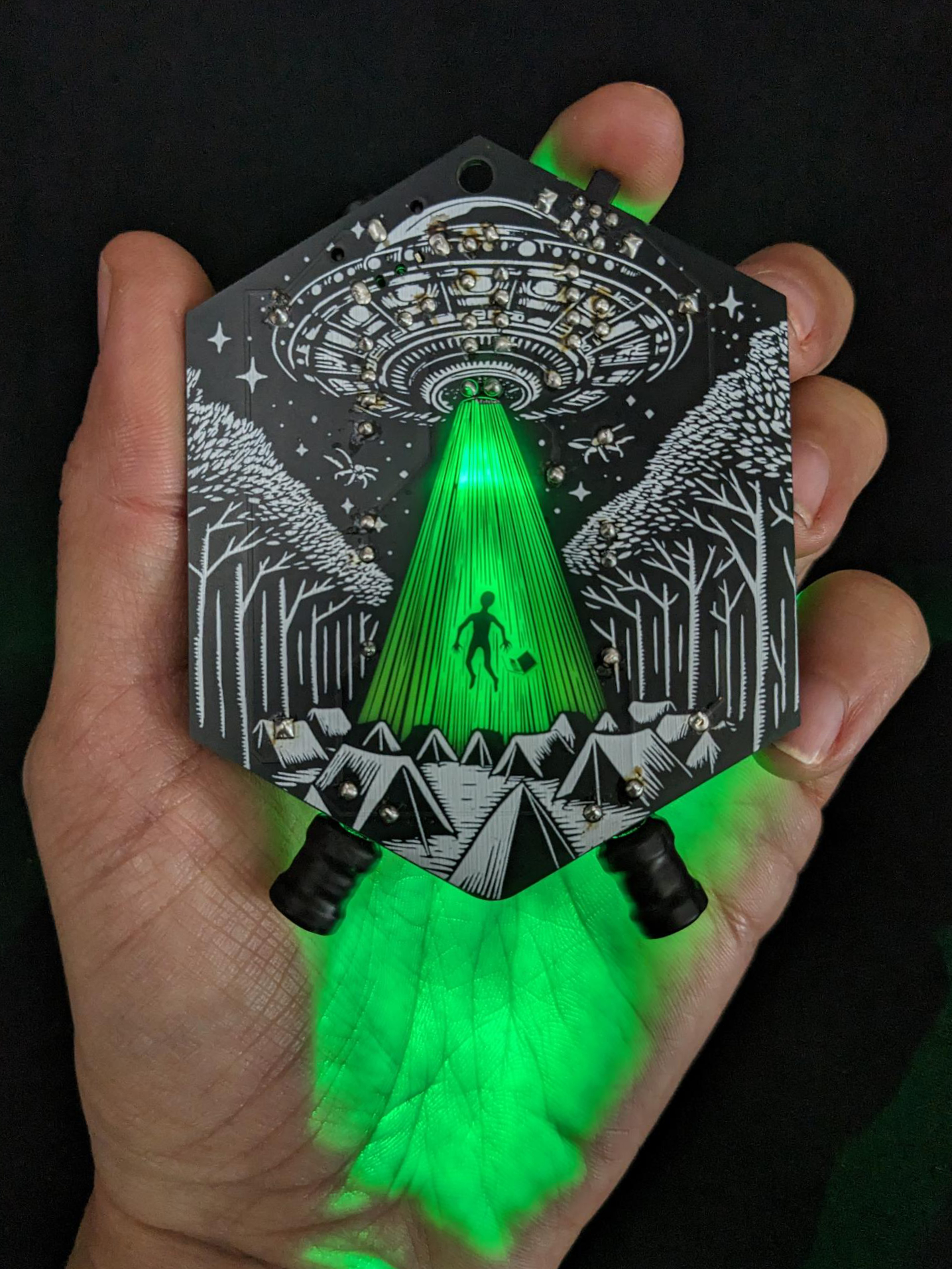
EMF Explorer Badge in Hand

Workshop Roadmap

How we will spend our time together today

1

The Science

~30 Mins

How electromagnetism works, the circuit concept, and soldering safety.

2

The Build

~60 Mins

Hands-on soldering. Assembling your EMF Explorer step-by-step.

3

The Listening

~30 Mins

Exploring electromagnetic sounds, troubleshooting, and KiCad art overview.

What is EMF?

EMF stands for Electromagnetic Fields. They are invisible areas of energy produced by the movement of electrical charge.

⚡

Everyday Sources

Our phones, laptops, screens, chargers, lights, power grids, anything that's powered on will produce EMF.

👂

The Audio Window

There is a huge range of EMF that we cannot hear without specialized equipment. Human ears can hear vibrations from about 20 Hz to 20 kHz. Luckily, all electronics cycle some of their energy within this exact frequency range.
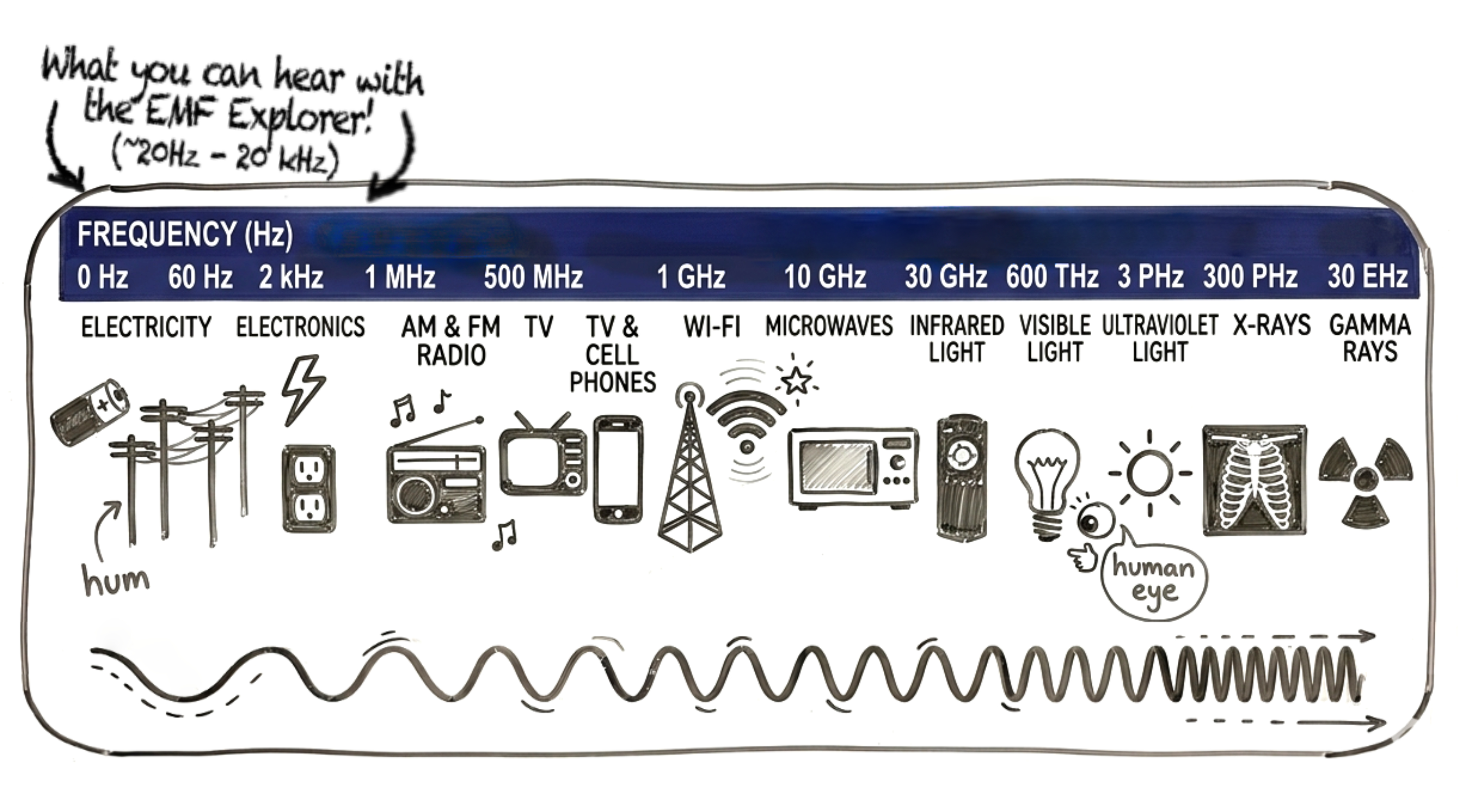
The Electromagnetic Spectrum
Electromagnetic Spectrum Chart
⚠️ Note: We cannot hear Wi-Fi or Bluetooth waves directly (they move billions of times per second). Instead, we hear the lower-frequency internal operations of the support circuits that produce those signals!

The Dance of Electromagnetism

Electromagnetism is governed by Maxwell's Equations, but for our workshop, we will be using our hears to decipher what we hear. For this process, we only need to understand two fundamental laws:

Ampere-Maxwell Law
Electric Current flowing through a wire creates a radiating Magnetic Field around it.
Faraday's Law of Induction
A Changing Magnetic Field passing through a coil of wire creates a Voltage inside it.
Interactive Maxwell Simulator
Current: AC Pulsing

How the Badge Works

The EMF Explorer acts as a translator, turning magnetic vibrations directly into electrical audio signals. Because the badge is low-power, you must bring it right next to the source. This is a feature: it lets you explore different parts of a circuit board to pinpoint exactly where signals originate!

1
Inductors (Antennas): Two wire coils pick up the changing magnetic fields (Faraday's Law).
2
Amplifier IC: A low-voltage operational amplifier boosts the induced voltages by ~1000x.
3
Headphones: The jack routes the boosted signal to your speakers, converting it back to physical sound.
Signal Chain Animation
Status: Auto-Animating

How a Speaker Works

Inside your headphones, the exact same physics rules are run in reverse to close the loop and hit your eardrum!

🧲

The Voice Coil

The headphone cable drives electric current into a tiny coil of wire sitting next to a permanent magnet.

📢

Diaphragm Vibration

As the electrical current fluctuates, it turns the coil into an electromagnet that repels or attracts the magnet, vibrating the cone to create physical air pressure waves.

Speaker Coil Mechanics
Frequency: 120Hz (Low Hum)

What Can You Hear?

Once built, explore these devices to hear their signature sounds

🔌

Wall Chargers

High-frequency switching regulators. Sounds like a chirpy whistle that changes pitch when your phone charges.

High Whistle
💡

LED Dimmers

Uses Pulse-Width Modulation (PWM) to dim light. Sounds like a harsh buzz that rises in pitch as you adjust brightness.

PWM Buzz
🏭

Transformers

AC voltage scaling. Emits a solid, steady 60Hz hum (50Hz in Europe) which is the baseline frequency of our power grid.

60Hz Bass Hum
💻

Laptop Keyboards

Keyboards and touchpads scan rows/columns constantly. Sounds like rapid rhythmic clicks, ticking, or digital heartbeats.

Digital Clicks

Let's Build: Badge Anatomy

Before heating up the irons, let's locate the components on your PCB and check their characteristics.

Direction matters!

Some parts can be inserted facing either direction, but some parts have "polarity" and need to be inserted in a specific direction. These polarized parts are labeled in red, so pay close attention when adding parts to your board. .

The IC (Op Amp Chip): Pin 1 notch must match the notch on the socket outline!
Switch, Electrolytic Caps, & AAA Battery Holder: Must align with the drawing on the silk board.
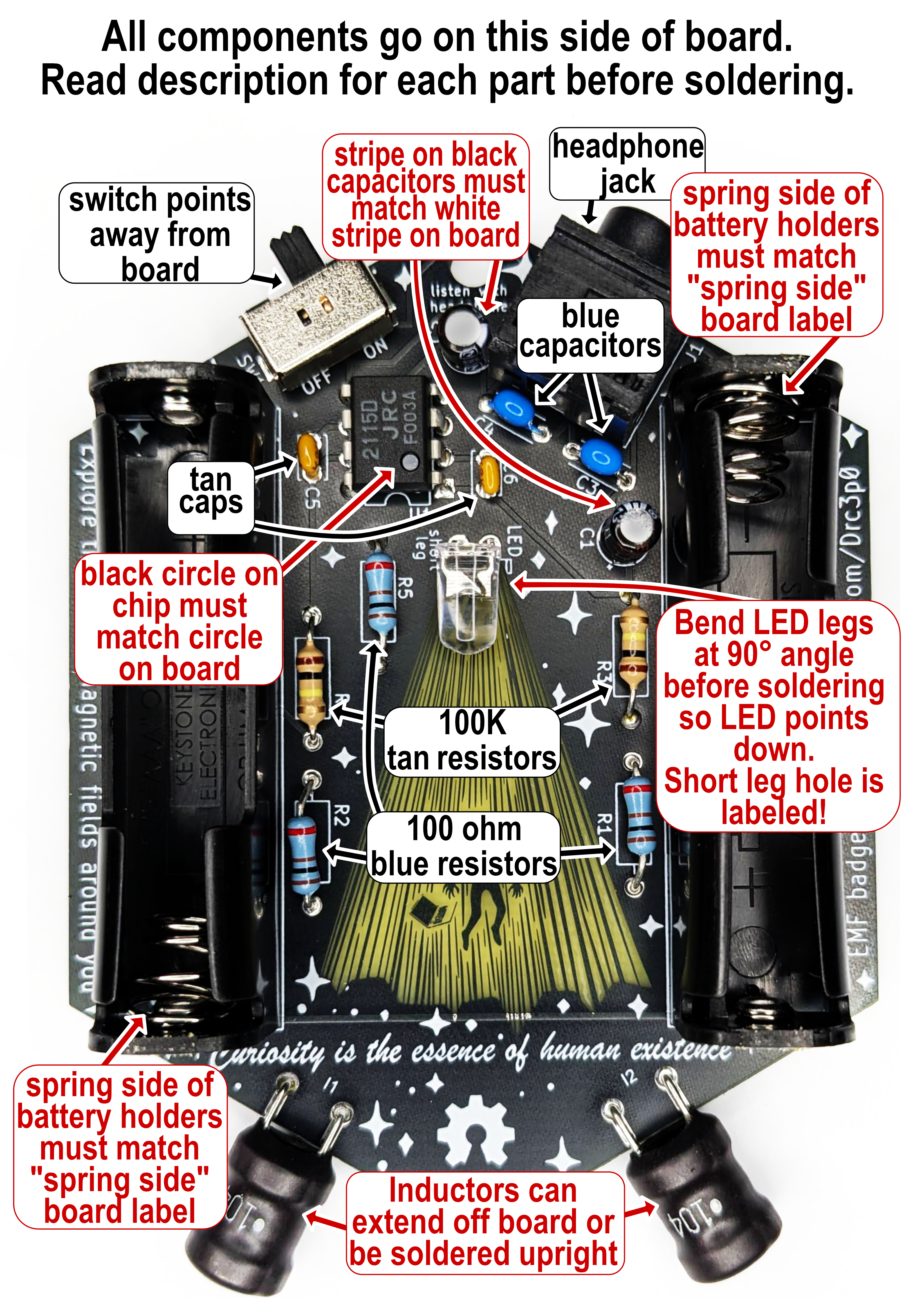
EMF Assembly Guide

How to Solder

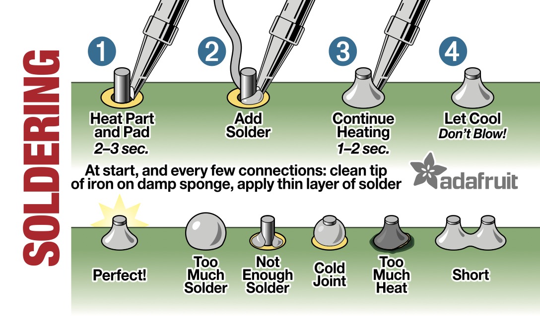
Soldering isn't gluing; it's a thermal bond! We use heat to melt metal (solder) into the tiny molecular spaces of the copper pads and metal leads, so that electricity can flow through these connections.

1

Heat: Press the iron tip against both the component lead and the PCB copper pad. Hold for 2-3 seconds.

2

Feed: Touch the solder wire to the joint, NOT directly to the iron tip. Let the hot parts melt the solder.

3

Release: Pull the solder wire away first, then remove the iron tip. Let it cool undisturbed.
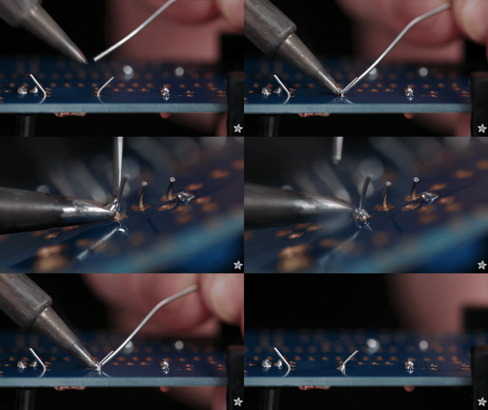
⚡ Soldering Tip: Keep your iron tip tinned (coated in fresh solder) to prevent oxidation and ensure good heat transfer!
Soldering Tutorial

Solder Quality Check

Inspect your joints before applying battery power!

Soldering Iron Tip Reference

💡 Tinning Tip: Keep the tip clean and tinned (coated with fresh solder). Touch the iron to both the copper pad and lead together to transfer heat efficiently.

Perfect Joint

Shiny volcano shape that coats lead and pad.

Cold Joint

Dull, grey ball that didn't flow. Easy to break.

Solder Bridge

Solder connects two separate pads. Creates short circuit.

Safety & Troubleshooting

⚠️ Safety First!

  • Ventilation: Do not breathe the smoke. Exhale gently while soldering to blow fumes away, or use a fume fan.
  • Lead Safety: Wash hands after soldering (solder can contain lead and other chemicals). Avoid eating/drinking at the table.
  • Wire Snips: Hold onto the wire leads when cutting or point snips downward/away from others when cutting wires so flying metal doesn't hit anyone's eyes.
  • Hot Iron: Always return your iron to a safe position when not in use. It is 300-400°C!

🔧 Troubleshooting Checklist

  1. Battery Check: Are AAA batteries facing the correct way?
  2. Headphone Test: Is your headphone plug pushed all the way in?
  3. Direction Check: Is the low-voltage op-amp chip inserted with the notch matching the socket's white print?
  4. Solder Inspection: Look at the back of the PCB. Are there any loose wires, empty pads, or solder blobs bridging connections?

💡 If it doesn't work right away, don't worry! We will find the bug together.

PCB Art, KiCad & Beyond

The EMF Explorer is a wearable piece of technology art.

🎨 How it was made: Created with KiCad, which is an open-source PCB design tool. KiCad. The art layers were drawn as vectors in Affinity Designer, then imported into KiCad layers using the Gingerbread converter. (gingerbread.wntr.dev)

🌱 Support This Workshop

Materials for this workshop cost $7-$10 per kit (prepaid out-of-pocket). We ask for donations on a sliding scale. Your contributions help make future workshops accessible for everyone!

📖 Scan to Learn More

EMF Guide QR SporkLogic Guide
GitHub QR KiCad GitHub
Make Magazine QR Make: Feature
Gingerbread QR Gingerbread

Let's Build!

Assemble and start exploring

1

Solder carefully! Double check component orientation (polarity) before soldering.

2

Show us your work for a quality check, and grab your AAA batteries!

3

Go exploring! Plug in your headphones. What objects in front of you can you listen to?

Soldering Reference Loop
EMF Assembly Guide Reference
Slide 1 / 12

Presenter Speaking Script